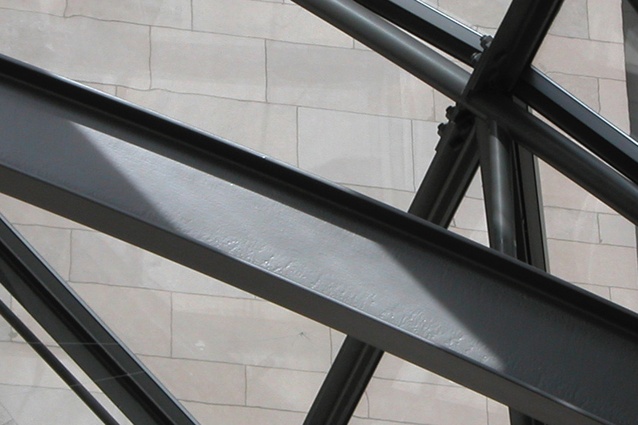
Architecturally exposed structural steel
In the lead-up to Sylvie Boulanger and Terri Meyer Boake’s lecture tour of New Zealand, the engineer and architect have 17 suggestions to help make designing with architecturally exposed structural steel an enjoyable interactive process and not just a challenge.
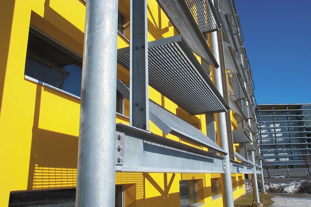
Architecturally exposed structural steel (AESS) is a mix of art, science and know-how, introducing the issue of ‘personal preference’ for what is considered aesthetically-pleasing, while remaining technically sound.
Whether your AESS project is the canopy of a retail store, the atrium in an office building, the passenger area of an airport, or the long-span roof structure of a sports complex, three key factors should be addressed to ensure a successful outcome: good communication, elegant connections, and reasonable cost. With AESS, the architect, structural engineer and fabricator form a triangle of communication, which greatly affects connections, their design and cost. This interactive design process is very different from the more linear process associated with ‘standard’ structural steel that is hidden from view and where the architect steps back from involvement in the process. When AESS is used, the architect sees the exposed connections as part of the design expression of the project.
Adapting to the new requirements in the design of AESS is not really that difficult and can actually be a fulfilling experience. We hope that the following suggestions will help.
Communication
A fabricator once explained that an architect specified “nice-looking” connections with a “smooth” finish for the exposed part of a school. However, “nice-looking” connection and “smooth” finish mean something quite different to the architect, engineer and fabricator. Communication must be structured to provide a clear set of guidelines for the vision of the outcome of the AESS project. Consider the following points to improve communication right from the specification:
1. Ensure the engineer includes an AESS subsection in their Structural Steel Specification. The AESS section will provide separate requirements for the exposed steel from what is normally included for concealed structural steel. However, all the standard structural steel requirements apply.
2. Adopt a category approach. A four-category system (AESS1 through AESS4) such as is now part of the New Zealand Steel Structures Standard NZS 3404.1:2009, can help clarify requirements for differentiating AESS as a function of the building type, distance of view, surface treatment and budget. The Australia/New Zealand Guide for Specifying Architecturally Exposed Structural Steel has been developed by the authors. This document provides additional explanation of the category approach and descriptions of the important factors of influence of AESS such as connections and finishes. It also includes information on protective systems (fire protection and corrosion) and coatings. Most importantly, the guide is an illustrated document filled with visual references.
3. Moderate discussions with the engineer and the fabricator in the early stages. It is essential that the architect, engineer and fabricator have face-to-face meetings to discuss expectations of the form, fit and finish of the steel. Depending on the work, it may be desirable to meet at the fabrication shop or in front of AESS that has previously been completed by the fabricator.
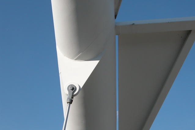
4. Be clear in the design documentation about what is acceptable as a substitution. Once structural requirements have been met, limits need to be placed on the range of members used in the structure. For example, the surface of a hollow steel section (CHS/RHS) manufactured to different standards may not be the same, and a helical weld has a different look than a longitudinal weld on a large tubular member.
Connections
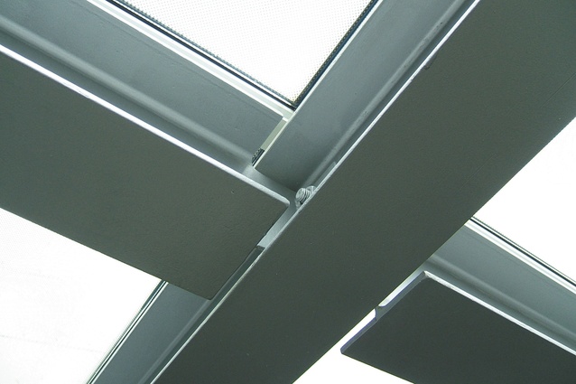
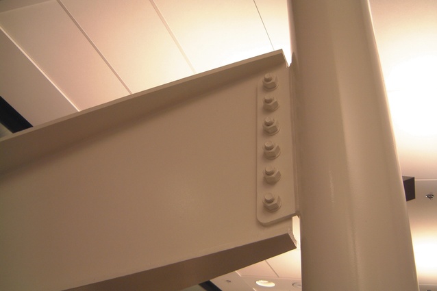
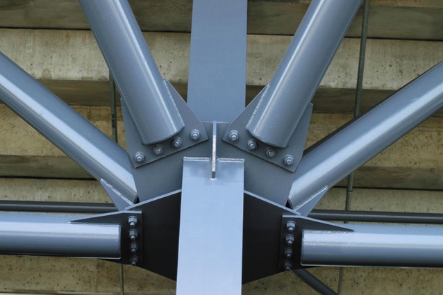
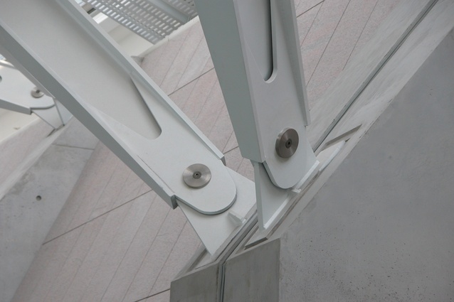
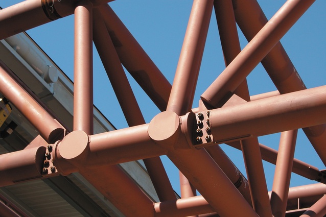
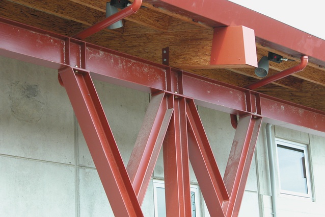
An award-winning fabricator with several successful AESS projects to his portfolio had this message for designers: “If they [designers] could spend some time making the connections more elegant, simplifying them so steel is used only where it’s really needed, that would help express steel’s attributes effectively and aesthetically.” Connections that are to be exposed must be designed differently than those that are concealed. It matters a great deal if the overall design will use bolted or welded connections. The connection design will inform and be informed by the overall requirements for the design of the structural system, as part of the architecture. Aside from specifying on which side of the connection the bolt heads should appear, consider the following suggestions to improve the integration of the connections in the structure.
5. Make stitch welds continuous. For longer distances, the same visual effect may be achieved by using caulking.
6. Reduce the number of pieces used in connections, including stiffeners. For example, consider using a web plate or single plate, instead of double angles or several plates. Another option could be making the web thicker and eliminating the need for a stiffener, or applying a stiffener only to the less visible side.
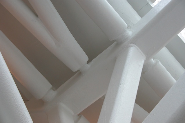
7. Modify the elements in or near the connection with rounded, tapered, curved edges. For example, apply a taper on the top and bottom flanges of an I-section, or round the corners on a shear tab or other plate element.
8. Minimise the gaps between the pieces and make sure they are consistent. For example, apply a maximum gap of 5mm. Large gaps and inconsistency result in a messy appearance.
9. Redesign obtrusive spliced bolted connections and complex field welded connections into more discrete bolted connections. As one example of this, the splice plates between CHS/RHS members could be designed in the longitudinal direction rather than in the transverse direction and bolted all around.
10. Hide as many burdensome details as possible. In a large truss, one may be able to do this by turning the CHS/RHS longitudinal weld away from view, or choosing CHS/RHS members that will connect nicely together by avoiding large eccentricities or requiring additional plate reinforcements.
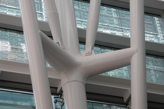
11. Consider using an aesthetically-pleasing casting as a connecting element. This option may be economically feasible when the cost of fabrication exceeds four times the cost of the steel in the connection, when you have high-stress concentrations or seismic requirements at a node and when there is repetition to amortise the cost of developing the mould.
Cost
When architects and engineers ask fabricators how much an AESS structure will cost compared to standard structural steel, the typical answer is, “it depends”. And the range can be great, from a cost premium of 25% compared to standard structural steel for a simple retail store to 50% for an atrium in an office building, and perhaps more than 100% for high-end airport structures. Be specific and communicate early on what exactly needs to be done. Realise that not all AESS need be created equal; understanding the impact of viewing distance and use, and allowing the fabricator to use simpler methods, can reduce some costs. Keep in mind the following tips to control and reduce cost.
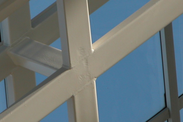
12. Specify a minimum surface preparation of Sa2 to AS1627.4. Insufficient surface preparation has often translated through the finishes and impaired the final product resulting in additional cost.
13. Take into account the final coating, fire protection or corrosion protection system before specifying surface treatments. There is no need to fuss over details if they are to be covered by a thick intumescent coating. Conversely, if the desire is for a high gloss finish, surface imperfections need to be minimised.
14. Avoid excess grinding and other surface treatment in remote or less visible locations. In other words, apply the 6m rule. If you can’t see it, such remedial surface treatment is unnecessary.
15. Avoid specifying samples that are expensive. Be reasonable and detailed on the kind of sample truly needed. Indicate whether it’s a 3D rendering, a small physical sample of steel with the finish applied, a ‘first-off’ inspection, a scaled-down mock-up of a detail or assembly, or a full-scale mock-up that remains for the entire job.
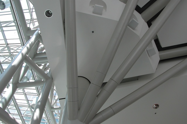
16. Check for availability, especially if large round tubes are used. This can delay the project and add cost for specialty work. The largest round CHS that is widely available is 457mm in diameter and generally not rolled as often as smaller tubes.
17. Don’t over-specify. Not all AESS steel need be created equal. Many lovely AESS projects are an amalgam of standard shapes, attentively-designed details and a simple coating system.
This article is published with permission from the editors of Modern Steel Construction magazine. The original version appeared in the December 2011 issue.
Sylvie and Terri will be presenting to New Zealand architects and engineers in the first week of November as part of an Architecturally Exposed Structural Steel speaking tour. For details of these events please visit the Steel Construction New Zealand www.scnz.org.

